Making a Document that Generates 3D Objects

To create a document that generates 3D objects, all you need to do to get started is state that you are generating a 3D object in the document’s body. The Logic API will automatically handle the rest. 3d demo

Step 1: Creating the document

As an example, let’s make a document than can generate simple 3D objects from text descriptions. To make this document that generates 3D objects, we can use the following content:
From a text prompt, generate a 3D model of the object described. Return the object as the text as a .obj file.

Step 2: Testing this iteration of the document

Using the Preview button, we can test this document to see if it works as expected. The document will generate a 3D object based on the text prompt provided. For the first iteration of the document, we have a few issues. The document was able to generate a 3D object, but it was not able to return the object as a .obj file. Instead, it returned the object as a text string encoded in base64. Once the base64 content is decoded and imported into a 3D viewer, I saw additional issues. The object was missing some faces, and had some other faces that were not visible, as they were facing the wrong direction. This is a common issue with 3D objects, and it can be fixed by flipping the normals of the object.

Step 3: Improving the document

To improve the document, we can add more specific instructions to the document’s body. For example, we can specify that we want the document to return the object as the text contents of an .obj file, and that we want the document to make sure all faces are visible and facing the right direction. To do this, we need to offer a few more details in the document’s body. I added a description of the .OBJ file format, and a few details about how the direction of the faces are handled in the .OBJ file format.
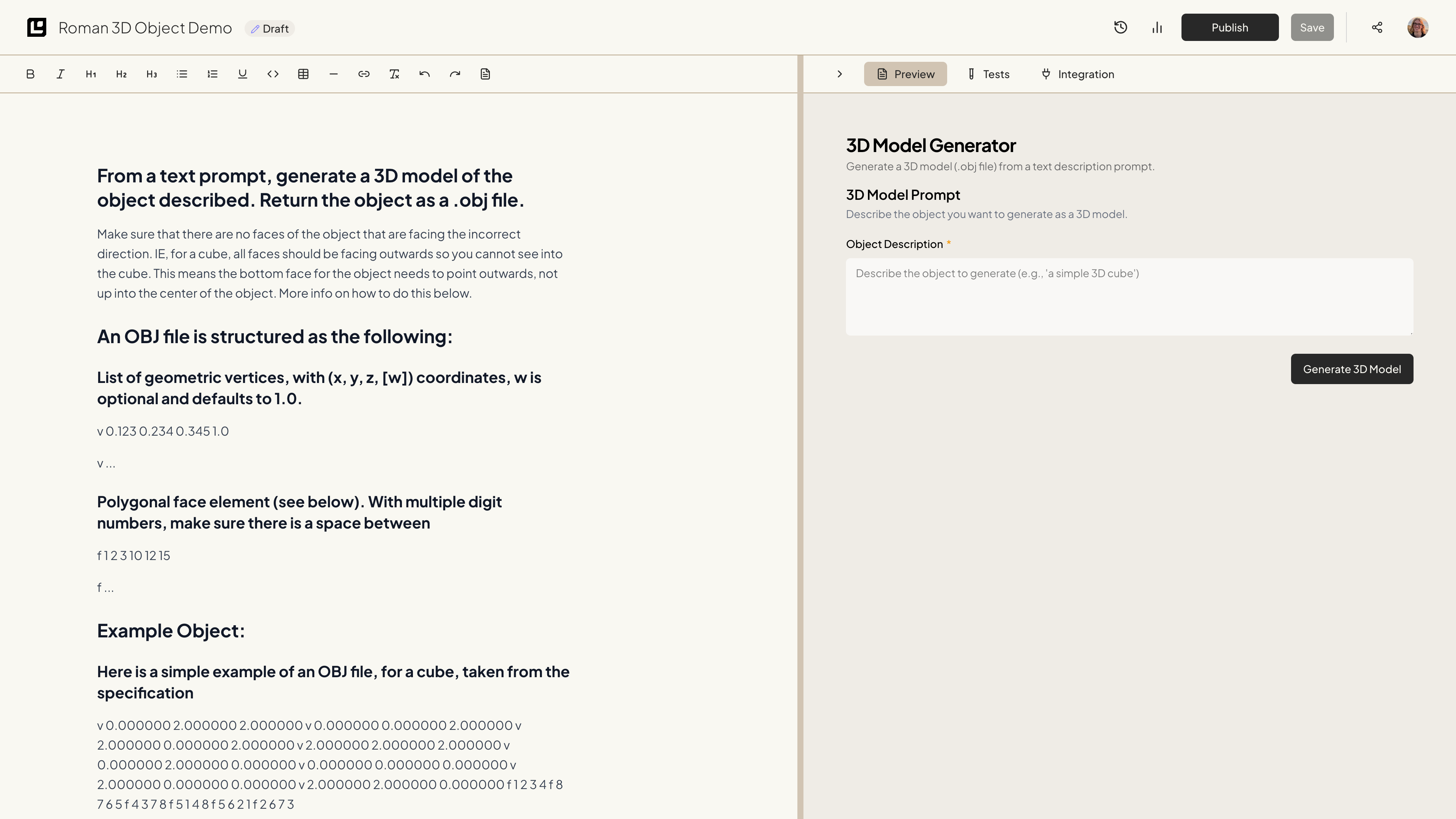
## From a text prompt, generate a 3D model of the object described. Return the object as a .obj file.

Make sure that there are no faces of the object that are facing the incorrect direction. IE, for a cube, all faces should be facing outwards so you cannot see into the cube. This means the bottom face for the object needs to point outwards, not up into the center of the object. More info on how to do this below.

## An OBJ file is structured as the following:

### List of geometric vertices, with (x, y, z, [w]) coordinates, w is optional and defaults to 1.0.

v 0.123 0.234 0.345 1.0

v ...

### Polygonal face element (see below). With multiple digit numbers, make sure there is a space between

f 1 2 3 10 12 15

f ...

## Example Object:

### Here is a simple example of an OBJ file, for a cube, taken from the specification

v 0.000000 2.000000 2.000000
v 0.000000 0.000000 2.000000
v 2.000000 0.000000 2.000000
v 2.000000 2.000000 2.000000
v 0.000000 2.000000 0.000000
v 0.000000 0.000000 0.000000
v 2.000000 0.000000 0.000000
v 2.000000 2.000000 0.000000
f 1 2 3 4
f 8 7 6 5
f 4 3 7 8
f 5 1 4 8
f 5 6 2 1
f 2 6 7 3

### For this example, if a user asked for "a simple 3D cube", you would return

"v 0.000000 2.000000 2.000000
v 0.000000 0.000000 2.000000
v 2.000000 0.000000 2.000000
v 2.000000 2.000000 2.000000
v 0.000000 2.000000 0.000000
v 0.000000 0.000000 0.000000
v 2.000000 0.000000 0.000000
v 2.000000 2.000000 0.000000
f 1 2 3 4
f 8 7 6 5
f 4 3 7 8
f 5 1 4 8
f 5 6 2 1
f 2 6 7 3"

## To Prevent Faces on Objects Facing the Incorrect Direction:

Wavefront .obj files assume a counter-clockwise (CCW) winding order for defining the "front" face of a polygon. This determines the direction of the face normal, which affects how it is rendered, especially with lighting and backface culling.

### In the case of an object with the vertices of:

v 0.000000 0.000000 0.000000

v 1.000000 0.000000 0.000000

v 1.000000 1.000000 0.000000

v 0.000000 1.000000 0.000000

v 0.500000 0.500000 1.000000

### This entry in the .obj file would make this face point up, as it is clockwise when viewed from above:

f 1 2 3 4

This is fine for making the top of an object, but...

### If making the bottom of an object, we would want this to be:

f 4 3 2 1

As this would be CCW when viewed from below

Step 4: Testing this New Iteration of the Document

With all of these updates, the document was able to generate a 3D object based on the text prompt provided. The document returned the object as the text contents of a simple .obj file, and all faces were visible and facing the right direction.

Conclusion

In conclusion, creating a document that creates a 3D object is easy with the Logic API. By simply stating that you want to generate a 3D object in the document’s body, the Logic API will automatically handle the rest. You can correct and improve the document by adding more specific instructions to the document’s body. This will help the Logic API understand what you want the output to look like, and how to fix any issues you run into. Now, you can publish your document and begin using the API to generate simple 3D objects.